Kitchenette light

The kitchenette light in my apartment looked ugly, and was longing for a much brighter, high-CRI replacement. Here I describe my somewhat succesfull attempt at building a new one, in a logical order.

Contents

Goal

Make an LED light strip, with the heatsink the length of the cupboards above, place a power adaptor in the middle of it where the power cable leaves the wall. Use two rows of LEDs, which means four segments.

Parts

Tools used

Listed in detail to relay my sense of absurdity.

  • mitre box, saw, files, Dremel 4000 + A576 sanding/grinding guide, vacuum cleaner

  • air purifier, earmuffs, safety goggles

  • cordless drills, {1, 2.5, 3, 4} mm drill bits, M3 screw tap, 4–22 mm step drill bit

  • PH1/PH2/flat-head screwdrivers, HCS8 6-4A crimping pliers

  • TS80P soldering iron + TS80-D25 tip, brass sponge, silicone soldering mat, tweezers

  • rosin core solder wire, tacky flux, isopropanol, cotton swabs, toilet paper

  • laboratory power supply, multimeter

  • snap-off blade knife, cable cutters, flush cutters, scissors

  • laser level, digital caliper, tape measure, ruler, sharpie

Power measurements

Of course, I’ve been lied to with parameters, but I hope at least the CRI is correct:

Stripe V drop @ 2 m Amps @ 2 m Declared width Measured width Declared W·m-1 Measured W·m-1

Cold

12 → 11.7 V

1.5 A

10 mm

10 mm

9.6 W

9 W

Daylight

12 → 11.6 V

1.35 A

10 mm

8 mm

9.6 W

8 W

The PSU has a sufficient ‘safety factor’ of about 1⅔, after accounting for everything, though note that the power consumption very slightly increases with temperature:

Length Power Amps Load

Output


40.0 W

3.30 A


Combined load

2.0 m

34.2 W

2.85 A

85%

Combined load

1.6 m

27.3 W

2.28 A

68%

Combined load

1.4 m

24.0 W

2.00 A

60%

Length adjustment

The target length was 1604 mm. Stoppers are 4.5 mm wide, with over 2.5 mm of internal space for the diffuser to slide in. Thus parts needed to be cut as following:

  • Heatsink: 1604 - 2 × 4.5 = 1595 mm

  • Diffuser: 1595 + 2 × 2.5 = 1600 mm

They were both easy enough to cut in a plastic mitre box, although edges weren’t exactly precise. The heatsink ended up being about 1 mm longer than I wanted, which was still okay. I naturally filed away sharp edges.

Heatsink adjustment

First off, protective tape needed to be removed. It might have been a better idea to use an unpainted heatsink—​the protective tape annoyingly doesn’t cover the full width, and the paint makes it much harder to slide in stoppers. It’s simply not worth the aesthetics.

The power cable was ø 7 mm, so I wanted to make a ø 10 mm hole for it, and managed to make a ø 12 mm hole instead. To find the exact placement, I had success with using a laser distance meter from both sides, but since I didn’t trust it, I carefully placed the heatsink over the cable, and made a mark with a sharpie.

PSU attachment screws needed to be placed precisely in the middle, which turned out to be a difficult thing to do. I had okay-ish results with pre-drilling holes using a 1 mm drill bit (and broke two of them by using too much pressure), then enlarging them to the 2.5 mm necessary for M3 screws, though they still tend to wander. Since I didn’t go for self-tapping screws, which would probably work fine for thin aluminium, I finished these holes with screw taps.

Four more holes needed to be added for wires to transfer 12 V to the other side of the heatsink, which conveniently has three appropriately sized channels on its bottom side (the middle one is for screws).

To attach the heatsink to the wall, I reused one off-centre screw hole that was meant for the PSU, enlarging it to ø 3 mm, then made ø 3 mm holes at the ends as well.

All holes were cleaned up with larger-diameter drill bits and files.

LED strips

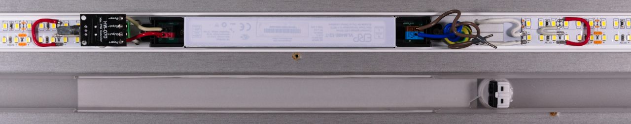
The LED strips are self-adhesive. However, once you attach them to the heatsink, you can’t reasonably solder on them. So I glued them in most of the way, then with them aligned next to each other added interconnects between the two adjacent rows of strips, deliberately avoiding having to solder any two wires together. Finally, I soldered in lead wires—​as already mentioned, one pair of them goes underneath the PSU. Coincidentally, my ø 12 mm mistake made it possible to slightly pinch it in place.

My 30 W soldering iron with its chisel tip generally did a good job, but I had to use some additional flux for proper reflowing, no matter how much I hate getting rid of residues. I wish I could hold tweezers, a soldering iron, and solder wire at the same time.

I tested both halves with a multimeter for shorts, + against – against un-galvanised parts of the heatsink. One half showed a resistance of around 15 megaohms between poles, which I could live with. Then I used a laboratory power supply to test function, and I knew it would be bright. It also told me the strips consumed about 23 watts together.

I connected the lead wires from each side to the target PSU using WAGO splicing connectors, so that I could avoid soldering. Initially, I wanted to try crimping the halves together, but the result wouldn’t even fit in the PSU’s clamps. My improvised solution takes up a lot of space, but at least the connections are solid, and undoable.

As a sidenote, I expected that if I used red wires buried deep underneath the diffuser that they wouldn’t be visible, but this isn’t exactly the case. There is a definite red tint around my interconnects, and components are also faintly apparent.

Diffuser adjustment

I found that the power adaptor didn’t leave enough space for the diffuser to slide in, so I had to remove the snap-in edges. The diffuser is made out of a rather hard, brittle material, so I couldn’t reasonably do this job with a knife or a file. Out came the Dremel.

Initially, I tried to remove just the snapping edge itself, using the A576 guide, but that wasn’t enough, so I had to cut off the inner part of the diffuser altogether. I’ve learnt that there is a bad direction in which to cut—​the material needs to be pushed away, or it will heat up and foam like crazy. At the end of this exercise, I was covered in small particles of plastic, and the air smelt of it as well.

To make a hole for the mains switch, I again used a step drill bit. However, I tried to push the switch in with too much force, and the diffuser cracked. Bother.

Finally, to cover up the electronics and various scratches, I used a strip of self-adhesive vinyl. Originally, I wanted to paint the diffuser from the inside, but it would keep all the imperfections I’ve made visible, and painting is a nuisance anyway.

Mains wiring

I carefully placed and screwed in the mostly-finished heatsink with the help of a laser level. The assembly is really light, so it doesn’t need particularly large screws. Conveniently, I could lay the diffuser on the mains sockets right below, so the switch could be kept in close proximity for wiring it up.

The existing CYSY cable had to be shortened, and stripped of its outer insulation layer. I wrapped the PE wire around one of the screws holding the heatsink to the wall, earthing it. The other wires conveniently happened to be just 0.75 mm thick, so the rest was easy. The live wire had to go through the switch mounted in the diffuser. Earlier, I found out that the switch really didn’t like to give up tinned wires once they were pushed in, and without tinning them I’d probably fail at trying to insert them in the first place, so it was crucial to crimp them.

Result

Original state of despair
Figure 1. Inherited state of sadness
New order
Figure 2. New order—​clearly, other things had happened to the kitchenette

The light was really, really bright, and positioned too low, thus it got a bit blinding once I took a step away from the kitchen unit. It ran cool enough, contrary to my expectations. Not great, not terrible, certainly an improvement.

Adjustments

Because I couldn’t figure out a reasonable design for a shade, I went through the pain of fitting a small PWM dimmer within the diffuser, replacing a pair of WAGO connectors. Its PCB turned out to be a bit too wide, so I had to take out the Dremel again, and extend the cutout I had made before. This time, I used it only as a cutting tool, on lower RPM, and removed the remaining little ridge with a file—​this was much less messy, and the result looked a lot cleaner.

I also swapped the module’s terminal block for a more convenient one, finding out just how bad I am at desoldering. And I upped the PWM frequency to about 50 kHz (220p capacitor) from the roughly 300 Hz (33n capacitor) the module had initially.

As the last finishing touch, I changed the vinyl to be not white but grey, as it stood out too much (it happened to be what I had on hand initially).

Adjusted light fixture

Takeaways

  • For really bright lights, you probably want a properly set-up dimmer. Or, with multiple strips, make it possible to switch some of them off.

  • A badly positioned light is a bad light—​in particular, it shouldn’t shine into your eyes.

  • Diffusers don’t diffuse all that much, things behind them are visible.

  • Anodized aluminium doesn’t conduct electricity.

  • Painted heatsinks are generally a poor choice.

  • There is a bad direction to dremelling plastics.

  • CYSY cable sheats are soft and easy to strip with a knife.

  • PWM dimmers are often sold running at awkward frequencies.

  • Be gentle with brittle plastics.

Comments

Use e-mail, webchat, or the form below. I'll also pick up on new HN, Lobsters, and Reddit posts.