All filaments release
measurable volatile organic
compounds when printing, as well as nanoparticles, and I plainly felt something
wrong with my lungs, even with PLA and PETG. Moreover, I wanted to try ASA,
which besides reportedly smelling much more requires stable temperatures.
I needed an enclosure.
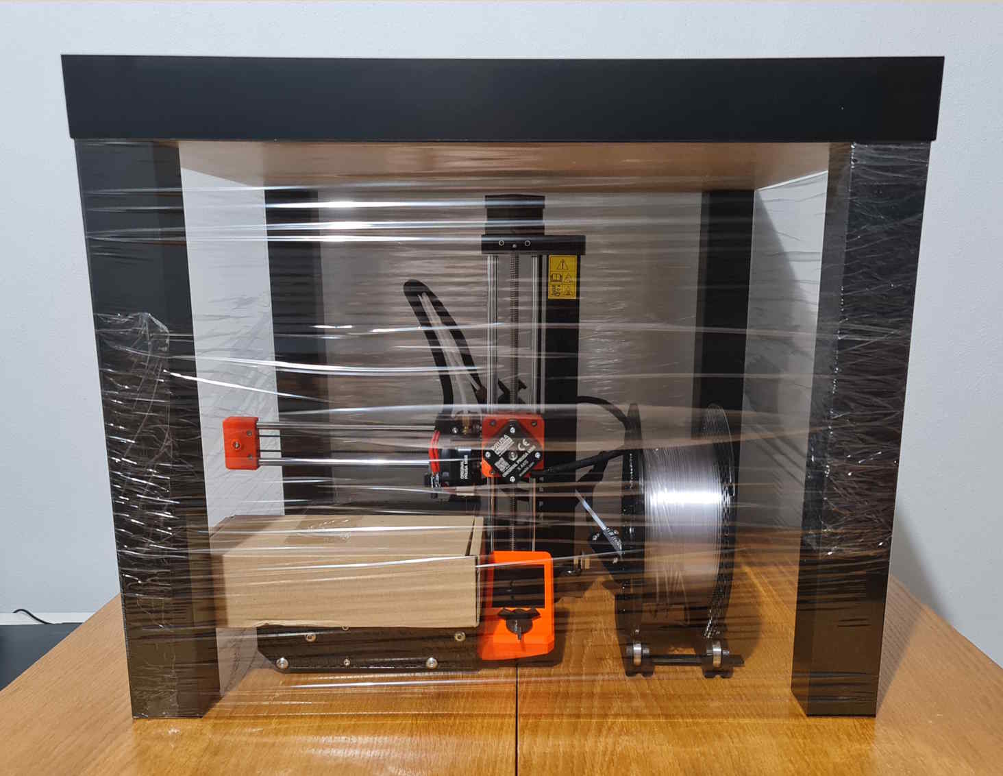
While thinking about how to go about this, I made a trivial enclosure from
an IKEA LACK table and some food wrap. While it prevented dust from falling
onto the printer, it was otherwise perfectly useless, what with its impractical
size and weight. Also, simply stacking them wouldn’t give me enough room to put
things underneath.
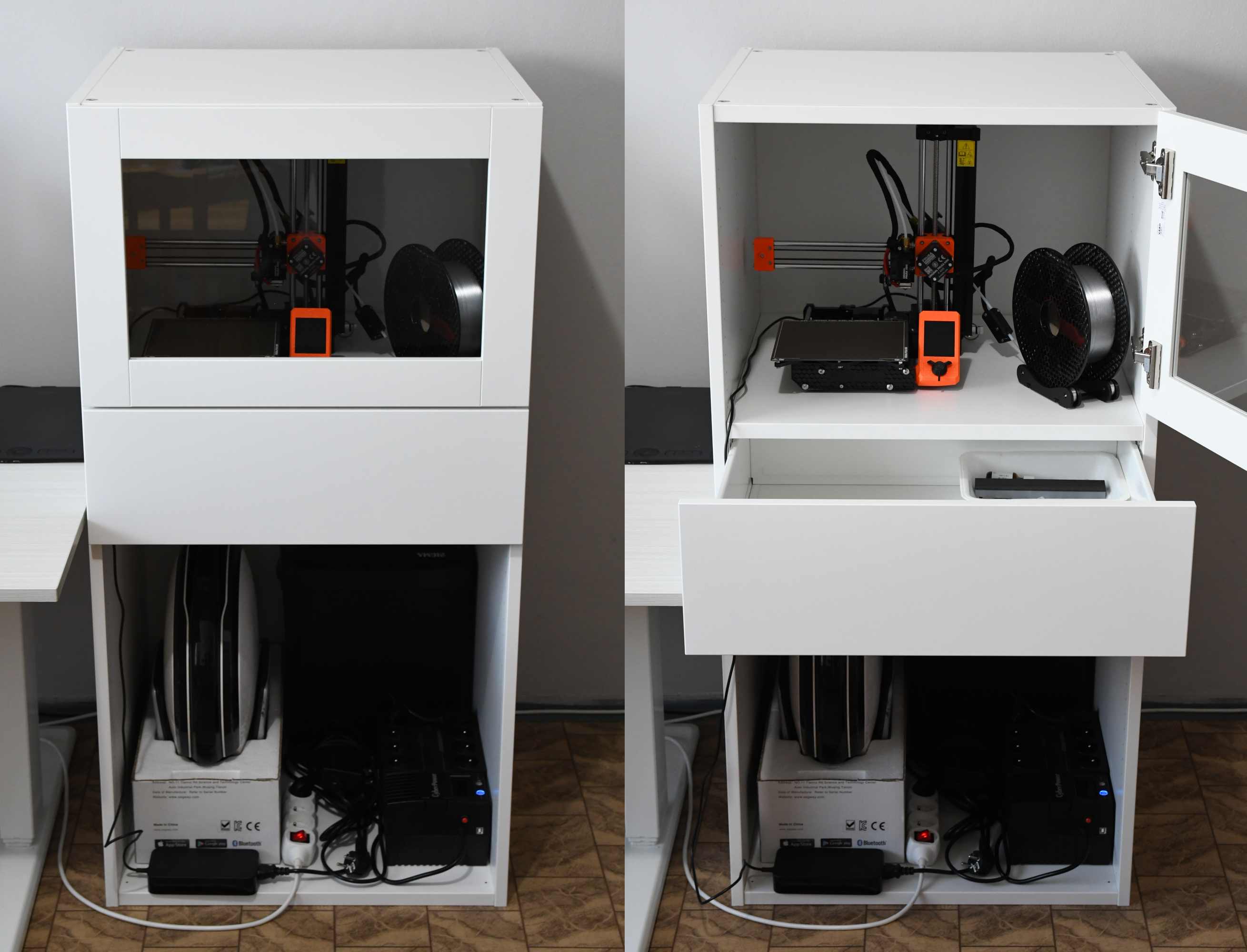
After some research, and looking through the IKEA e-shop, I arrived at the
decision to formalize my impromptu ugly stack of things in the form of
a PLATSA-based build. And I got it right only due to sheer luck—while
the 40 cm high glass door I picked was insufficiently high to cover the whole
printer, the drawer front had an alternative, lower groove for the bottom, which
enabled me to cover exactly the blank space above it. Very little space is
wasted.
The quality is sadly appropriate for the low price, in that the door had some
resolvable issues with closing flush, because the side walls of the assembly
warp outwards under load, and the freely hanging shelf is unable to hold them
together.
The bottom part is open intentionally, in order to help dissipate heat from
power adapters, and charging devices.
Upgrades
I applied some unused
foam tape to seal the huge air gaps
around the door at least the tiniest bit better—it even looks nicer that way.
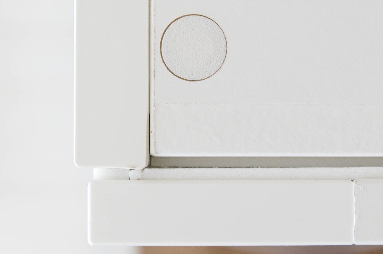
Similarly, I had to
mask
the ugly connecting screw holes—for that I used Prusament ASA "Signal White",
which is actually just regular boring white and roughly matches the paint on
the frame.
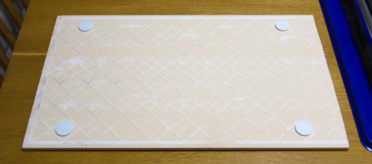
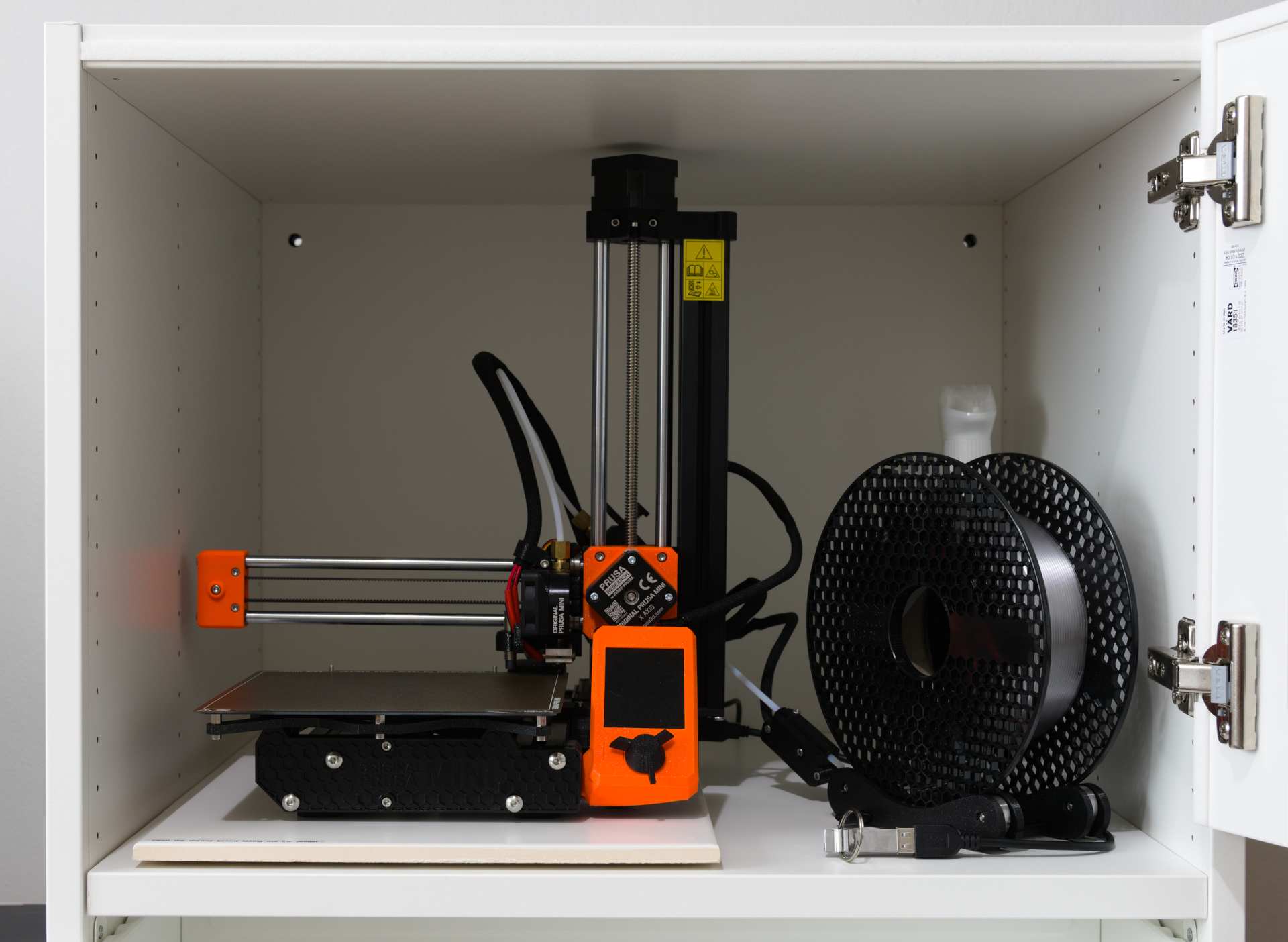
Due to insane resonation levels, I’ve placed the printer on a
tile
that I cut with
a cheap cutter
to about 51 cm of length (the shelf is 52.5 cm long), supported by a few
rather dense felt pads,
as felt is known to have good sound insulation properties. Originally,
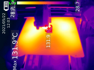
with stock Průša feet, there were exactly 2 cm of vertical space left above
the Z axis stepper motor—the padded tile reduced that to 8 mm, which is rather
acceptable. (Note that the Z axis will be slightly limited in movement, as the
PTFE tube and cable bundle will start to bend at the height of about 130.)
As for the practical results of this exercise, purely subjectively judging, it
seems to have helped, reducing the direct transfer of vibrations a great deal.
More empirically, when printing with the glass door closed, I measured 52 dBA
max just outside of it.
There is also a 50 cm USB 2 extension cable now (theoretical maximum 60 MiB/s,
therefore more than sufficient for G-code), since trying to find the hole was
fairly anoying even without the enclosure, and the keyring tended to make noise.
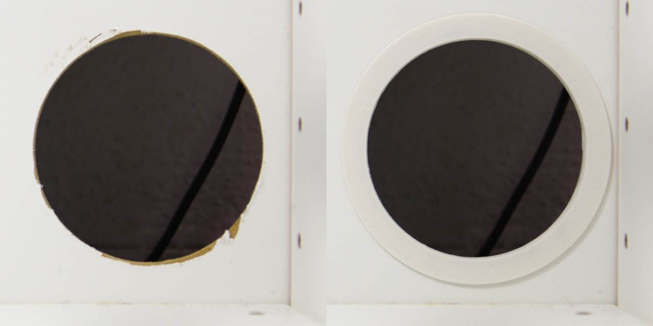
To tidy up the cabling, I used a hole saw to make a ø 5 cm hole in the back for
my UPS’s power cable, though ø 45 mm would have more than sufficed. Power plugs
are less than ø 40 mm. To make the slightly botched opening look nice, even
though it stays hidden at all times, I’ve printed a perfect bushing, and glued
it in place with PVA glue:
Next, the back panel flexed a bit too much, and there was about 16 mm of space
behind it to put a support in. I cut off a piece of a rectangular 20 by 5 mm
aluminium profile, and stuck it there using double-sided tape. The profile
proved to be quite difficult to cut with hand tools, yet at the same time it
hasn’t stopped the flexing—I should have went for something even more rigid.
With this in place, I had to make the printer’s power cable go
through the middle of the shelf—I cut a semi-circle-ish shape with a jigsaw,
filed it into something better resembling a semi-circle, then printed an
appropriate grommet.
Lighting
Calculations
I found a PSU that could be used to power the light, but it gave 12.19 V, and I
wasn’t sure if that value is okay. People claim successfully using LED strips
in cars, where the voltage can be as high as 14.5 volts, but that still doesn’t
provide much confidence.
So I ran the numbers. Going by per-module resistor values, different for each
of my two strips, the current cannot be more than (12 V / 180 Ω =) 66.666 mA
or (12 V / 200 Ω =) 60.000 mA, but this is further reduced by the diodes.
In particular, when assuming a voltage drop of 3 volts per diode, a somewhat
typical value, the target current is about ([12 - 3 * 3.0] V / 200 Ω =) 15 mA,
way below the listed "absolute maximum rating" of various 2835 LEDs one can find
on the Internet.
In general, mildly higher voltages affect life span, but they’re nothing to
worry too much about—the bigger concern is proper heat dissipation.
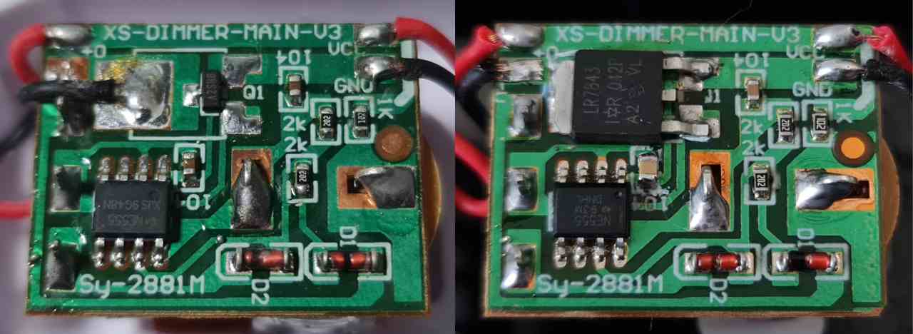
Dimming
Since the light strips are unnecessarily powerful, I ordered
a basic dimmer from
AliExpress, which has caused me considerable pain—never mind that it contains
a very weak MOSFET that will burn on
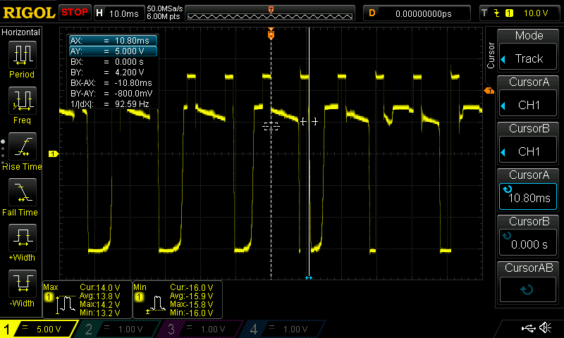
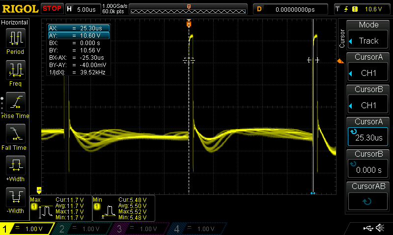
higher loads, but the switching frequency is set way too low, below 100 Hz.
Figure 2. Original dimmer output; no idea why it kept going down to –15 V
I’ve laboriously found out that the necessary frequency should actually be in
the order of tens of kilohertz, because:
-
100 Hz, equivalent to rectified 50 Hz AC, is about the very threshold of
sometimes being able to see lights flicker directly for most people,
but it’s a stroboscope.
With digital cameras, if the frequency isn’t exactly 100 or 120 Hz—which is
unrealistic with a 555-based circuit—or when you point them directly
at the light source, their anti-banding will fail. Multiple phase-shifted
light sources also break it. Moreover, SLRs without ‘flicker reduction’
may produce entirely black photos.
-
At 1 kHz, there is still a noticable stroboscopic effect—when I wave
my hand quickly in front of a light, I can see it in multiple copies,
and moving my eyeballs has the same effect on everything illuminated,
which is really annoying.
Wikipedia summarizes
this subject rather well.
-
At 10 kHz, my phone’s camera still shows the duty cycle as distinct vertical
stripes, and my DSLR as horizontal. It’s also within the audio range,
so you can get piezo noise.
The problems have mostly went away once I bumped the circuit’s frequency to
somewhere around 35 kHz. This change was rather simple to achieve, because
the board happens to use the familiar NE555 in its astable mode, so I kept
progressively replacing a nearby 100 nF SMD capacitor with lower values.
The winner was 220 pF.
First, I managed to attach a TK783 THT ceramic capacitor from my Tesla
stockpile, but then I bought a proper set of 0805 SMD capacitors—both can be
soldered onto 0603 pads just fine with a bit of effort. I had great success
with using flux, solder wick, and a knife tip to remove small SMD parts.
I actually kept experimenting with the frequency on separate test circuits, and
with LG Nexus 5X I’ve managed to find hints of aliased stripes even at 200 kHz,
which is ridiculous. My conclusion is that PWM should be avoided at all,
if possible, and I haven’t even touched
colour.
Otherwise, something between 20 and 50 kHz seems like a good compromise—higher
frequencies than that have diminishing returns, and you may start getting other
issues.
Of course, while trying to attach oscilloscope probes, I managed to short out
the cost-optimized transistor. I’m not sure how much current my 2A power supply
put through it, but it blew within seconds. Luckily, semi-blindly replacing it
with LR7843 has worked out
perfectly, and I no longer need to care about longevity. Notice how the proper
part costs 10 fucking cents per piece.
While I ended up using my hot-air station to seat parts properly, it didn’t
seem necessary, as you can solder the MOSFET’s tab from the side.
Figure 3. How the ‘Sy-2881M’ was, and how it should have been
Figure 4. New dimmer output at the lowest setting, looking sane
Well over $1000 in equipment to fix a $2 dimmer, and to get a bit of experience.
Future: Tuning
As already mentioned, the sides warp outwards, which could be resolved by
pulling them together in some manner—perhaps using a threaded rod or pipe.
I’d also like to
connect
the printer to the network again, however useless that is, or maybe just Wi-Fi
enable it.
I’d like to add a temperature and humidity sensor with a display (or see how
responsive analogue ones are). I could finally make use of my MSP430 dev board,
and get sensors from Aliexpress.
Air filter inspiration:
1,
2,
3.
People claim something as relatively simple as a HEPA + carbon filter even
on low fan speeds gets rid of ABS odours, so there’s probably no need
to overengineer. HEPA-rated filters can be most easily obtained for vacuum
cleaners
(1,
2,
3,
4,
5).
Active carbon can simply be bought
in pellets.
A large and powerful fan is approprate
(1,
2,
3).
PWM fan control would
be possible. I definitely need temperature regulation and ventilation for
longer ASA prints, not only to avoid damage to the printer, but also to prevent
spools themselves from getting too hot.
Any controls shouldn’t be put it in there with the printer. I can screw into
the premade holes in the side, below the drawer. Print a case using my signal
white ASA filament.
In short, this is a time sink, though the experience should be valuable.
List of usable parts at my disposal:
-
partial TI MSP-EXP430G2
LaunchPad development kit with
MSP430G2553, ±3.3 V
-
plentiful 7-segment THT LED displays: LQ425 ×7, LQ310, LQ410 ×2
-
I2C OLED module 3.3–5 V
would be a much simpler and nicer solution, I have two
-
plentiful switches, tiny and large
Comments
Use e-mail, webchat, or the form below. I'll also pick up on new HN, Lobsters, and Reddit posts.